Tools Menu
Summary
Vertices | Weld
Vertices | Split
Vertices | Reorder
Vertices | Displace
Normals | Smooth
Normals | Fix Seams
UVs | Stitch
UVs | Weld
UVs | Relax
UVs | Align U
UVs | Align V
Facets | Concave
Facets | Degenerate
Facets | Collinear
Facets | Align
Facets | Invert
Facets | Triangluate
Facets | Two Sided
Model | Scale
Model | Spherify
Model | Smooth | Subdivide
Model | Smooth | Catmull-Clark
Model | Smooth | Doo-Sabin
Model | Smooth | Loop
Seams | Deselect All
Seams | Show All
Seams | Set From UVs
Seams | Expand Loop
Seams | Set From UVs
Islands | Uniform Scale
Islands | Level Horizontal
Islands | Level Vertical
Islands | Tile
Materials
Statistics
Dimensions
Description
Vertices | Weld
This feature finds all vertices in the current model that are identical and replaces them with a single vertex. In programs that
perform smoothing based upon facet information, this will cause your models to be smoothed across edges that were previously split.
Vertices | Split
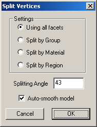
This feature operates on the current selection, or the entire model is no selection is active. Options include Using all
facets which will make no distinction between groups, materials or regions; Split by Group, Split
by Material, and Split by Region which will only split the vertices of facets that belong to the same
group, material and region respectively. The Splitting Angle determines the minimum angle between facets that will
remain unsplit, and therefore smooth. All facets that exceed this angle and satisfy the other conditions will be split.
Finally, checkng Auto-smooth model will cause the model to be smoothed with a Smoothing Angle of 180
degrees, which will smooth all facets that are unsplit. See also: Normals | Smooth (below.)
Vertices | Reorder
Use this command to reorder vertices that have been changed by another 3D modeling program. Some 3D modeling programs don't seem to
care what order the vertices of a model are in and will reorder them without mentioning a thing to you. As a result, when you try to use
the resulting model as a morph target the model explodes! To avoid this, load the model that's been edited with the ill behaved
3D program, select the Reorder option and specify the original model in the file dialog box. UVMapper
Professional will reorder the vertices in the currently loaded model based on the specified model so that it can once again be used as
a morph target, etc. If you're getting a message that says "Incompatible Facet Structure" use the "Generate
Report..." option under the file menu to compare the two models to see what the problem could be.
Vertices | Displace
Use this command to perform displacement mapping within UVMapper Professional. This command requires that a bitmap
be loaded into the background (see Texture | Load from the main menu.) This bitmap is the displacement
map and will adjust the geometry of the model based on the brightness of pixel beneath the texture coordinates for the
vertex. Selecting the Displace command brings up a dialog box with the following options:
Offset Method
Use this option to select the direction of the displacement for each vertex. You can choose to have the movement along the
vertex normal (outward from the model) or along the X, Y or Z axis.
Min Offset
This is the amount each vertex will move when the brightness of the underlying texture map is 0.0 (0 out of 255.)
Max Offset
This is the amount each vertex will move when the brightness of the underlying texture map is 1.0 (255 out of 255.)
Invert Offsets
Use this option to invert the brightness of the displacement map. This has the same effect as loading a negative image of the texture
map before performing the displacement.
Auto-smooth
Use this option to have UVMapper Professional automatically generate vertex normals after performing the displacement mapping.
See also: Texture Menu.
Normals | Smooth
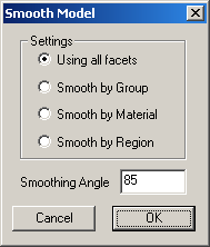
This feature is used to create vertex normals for the current model. Options include Using all facets which will
make no distinction between groups, materials or regions; Smooth by Group, Smooth by Material,
and Smooth by Region which will only smooth the vertices of facets that belong to the same group, material and region
respectively. Smoothing Angle specifies the angle below which two facets will be smoothed together. Facets
that have an angle greater than the Smoothing Anglewill exhibit a sharp edge between them after the smoothing has been
performed.
Normals | Fix Seams
This feature is used to average the normal vectors along the seams of a 3D model, allowing it to render smoothly. It was
originally written to solve a problem with models exported from Poser because that
program didn't originally combine vertices across groups. This bug has since been fixed.
UVs | Stitch
This feature will average all of the selected UV coordinates for a given vertex and combine them, setting them all to the average.
This has the effect of welding UVs together, but only the ones that share common geometry. It's a nice way of recombining
portions of a texture map that have been laid out seperately. To use this feature, you must be in Select Method |
by Vertex mode, and there must be a seleciton active. See also: Select
Menu.
UVs | Weld
This feature will average all of the selected UV coordinates and combine them, setting them all to the average. The
result will be a single UV coordinate in place of the entire selection. This can be used to manually piece together
portions of a texture map that don't necessarily share geometry. To use this feature, you must be in Select Method
| by Vertex mode, and there must be a seleciton active. See also: Select Menu..
UVs | Relax
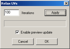
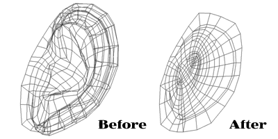
The Relax UVs feature is an extremely powerful tool for flattening texture maps. Selected facets or vertices are
pinned down and will not be able to move. If there is no selection active the entire map is free to move, which is usually not
desirable. Pressing the Apply button will start the process and perform the Relax UVs routine
Iterations times. To perform more iterations each time you press the Apply button, increase the
number in the Iterations box. You can halt execution at any point by pressing the Cancel
button. Pressing Cancel when the routine is not running will close the dialog box and undo any changes. Press
OK to close the dialog box when you are satisfied with the results. Selecting the Relax command
brings up a dialog box with the following options:
Iterations
Specify how many times to execute the Relax UVs routine each time you press the Apply button.
Enable preview update
As the Relax UVs routine progresses the texture template is normally updated to reflect the changes. If you would like to speed
up the process, uncheck this option and the texture map display will not be updated until all iterations are complete.
UVs | Align U
This feature sets the U coordinate of each selected vertex to the average U coordinate of the entire selection. This is
useful for aligning a line of texture coordinates horizontally. In order to use this, the selection mode must be either
Select by vertex or Select by edge. The selection mode can be set by selecting Select
| Select Method form the main menu. See also: Select Menu.
UVs | Align V
This feature sets the V coordinate of each selected vertex to the average V coordinate of the entire selection. This is useful for
aligning a line of texture coordinates vertically. In order to use this, the selection mode must be either Select by
vertex or Select by edge. The selection mode can be set by selecting Select | Select
Method form the main menu. See also: Select Menu.
Facets | Concave
This feature finds every concave facet in the current model and attempts to triangulate it so that it will render properly.
Problems can occur when the facet is not only concave but also non-planar. It is possible to have a facet that cannot be properly
triangulated with existing vertices. It's a good idea to use Select | Facets | Concave
before attempting to repair concave facets so that you can have a look at them and see what you're up against. See
also: Select Menu.
Facets | Degenerate
This feature finds and removes any degenerate facets in the current model. An example of a degenerate facet is a triangle that has
two identical vertices. The facet is said to have degenerated to a line. Degenerate facets can cause rendering problems because
it is impossible to determine which way such a facet it facing. If you are experiencing black marks or unexpected creases when
rendering your model, there's a good chance degenerate facets could be causing the problem.
Facets | Collinear
This feature finds and attempts to repair any collinear facets in the current model.
Facets | Align
This feature attempts to align every facet in the model based on the orientation of the facets surrounding it.
Facets | Invert
This will change the winding order and invert the normal vectors of every facet in the current selection, or the entire model if no
selection is active.
Facets | Triangluate
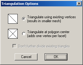
Triangulate the current selection, or the entire model if there is no selection active. This will result in a model that has no
facets with more than three sides, or vertices. You have the option to Triangulate using existing vertices,
which will result in a smaller mesh. If you are triangulating a model that is all quads (i.e. all of it's facets are four sided)
this option will double the number of facets in the model. Alternatively, you can select Triangulate at polygon
center which adds one vertex per facet. Triangulating a model that is all quads with this option will quadrouple the number
of facets, but it will also usually result in a smoother mesh. When you select Triangulate at polygon center, you
will also have the option Don't further divide existing triangles. Checking this will leave all existing
triangles alone.
Facets | Two Sided
Duplicate every facet in the selection, or the entire model if no selection is active, flipping each duplicate. This will result
in a model with twice the number of facets a before. Note: most rendering programs have an option to
render facets as two sided without resorting to duplicating them, so I highly recommend making sure that your rendering program does
not support rendering facets as two sided before using this feature.
Model | Scale
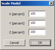
This feature scales the size of the entire model along the X, Y and Z axes. For example, 100 percent performs no scale, 200 percent
doubles the size along the corresponding axis, 50 percent scales it by one half.
Model | Spherify
This feature will adjust all geometric vertices in the model so that they are equidistant from the center, in effect making your
model spherical. This can be useful for smoothing out ecentricities in geosphere primitives after subdivision.
Model | Smooth | Subdivide
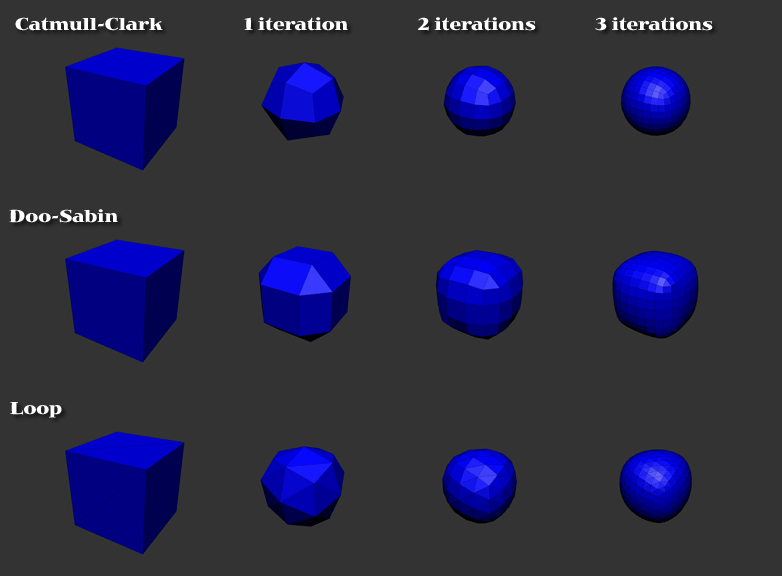
This feature will smooth the model using the selected method of subdivision surfaces; either Catmull-Clark,
Doo-Sabin or Loop. With the Catmull-Clark and Loop methods, it
will also subdivide the texture map so that applied textures need not be updated. The Doo-Sabin method generates new
facets between existing facets, and subdision of the texture map is not currently supported. Each iteration will increase the
number of facets in your model by approximately 4 times. On average, each facet is replaced by four new facets. Edges that
have been split using the Split Vertices feature are considered 'hard' and will remain so after smoothing.
See also: Vertices | Split (above.)
Model | Smooth | Catmull-Clark
Model | Smooth | Doo-Sabin
Model | Smooth | Loop
These menu items are used to select the desired method of subdivision surfaces. The three
options are Catmull-Clark, Doo-Sabin and Loop. Both
Catmull-Clark and Doo-Sabin can be used with polygons of any size (n-sided polygons.) The
Loop method requires that models be triangulated first. See also: Facets | Triangulate
(above.)
Note: many modeling programs use subivision surfaces (SDS) to create extremely organic looking
models. SDS can also be used to create more detail in models with a low polygon count. If some of your models are
collecting dust because you think they're not high enough resolution to use, drag them out and run them through this routine once or
twice. I think you'll like the results.
Seams | Deselect All
Deselect all currently selected seams. This option will clear all seams that have been selected. It can be reversed by
selecting Undo from the Edit menu.
Seams | Show All
Selecting this item will toggle between having the seams visible through the model in the 3D view, or not. If you're having
trouble visualizing which edges are selected on the entire model, toggling this should make it easier to view.
Seams | Set From UVs
This feature will select all seams that lie along the edges of a texture map. This makes it easier to maintain the seams
you've previously selected before performing a new LSCM mapping, e.g. after reloading a model that's been mapped previously.
Seams | Expand Loop
This feature will extend seams that have been selected to automatically create loops. It will extend seams until they either
connect to another seam, or they reach a vertex that doesn't have a clear choice for continuation. To best learn how this works,
I recommend selecting a single seam and trying it. You can always undo your last action using the Undo command on the Edit menu.
Seams | Split Seams
This feature will split the vertices for all selected seams. It has the effect of turning all red seams (seams that share common
vertices) into blue seams (seams that don't share common vertices.) This provides an easy way to divide up the model into separate
smoothing groups.
Islands | Uniform Scale
This feature will calculate the average size of the facets in each of the islands on the texture map and automatically scale them so
they will have as uniform a scale as possible. This is an easy way to resize the different sections (i.e. islands) so that the
texture map will be scaled properly across the entire model.
Islands | Level Horizontal
To use this feature, select two vertices in each island you would like to level. The island will be rotated so that the two
selected vertices are horizontal. Any islands that have less or more than two vertices selected will be ignored.
Islands | Level Vertical
To use this feature, select two vertices in each island you would like to level. The island will be rotated so that the two
selected vertices are vertical. Any islands that have less or more than two vertices selected will be ignored.
Islands | Tile
This is the same option that's available from the Map | Tile By | Island menu. See also: Map Menu.
Materials
This selection brings up the Material Properties dialog. See also: Material Properties.
Statistics
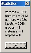
This selection displays the number of vertices, texture coordinates, normal vectors, facets, groups, materials and regions for the
current model. Note: these values are for the entire model, even when there is an active seleciton.
The dialog below is from the default built in sphere primitive.
Dimensions
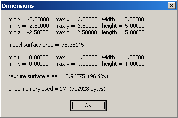
This selection displays the dimensions of the bounding box for the current selection, or the entire model if no selection is
active. All dimensions are in Wavefront (.obj) units. The minimum and maximum coordinates for each of the ordinal axes (x, y
and z) are given, as well as the overall width, height and length. Model surface area is also calculated and displayed.
Minimum, maximum, width and height of the texture map template is given, and the area of the facets on the texture map as compared to the
overall area is give. Note: this value may exceed 100% if you have overlapping facets. Finally, the
amount of memory currently in use by the undo system is displayed. A maximum value for the undo system can be set in the
Preferences dialog. The dialog below is from the default built in sphere primitive. See
also: Preferences.
